 English
 German
 French
 Spanish
 Portuguese
 Italian
 Polish
 Turkish
 Romanian
 Greek
Greek
 Bulgarian
 Russian
 Arabic
 Hindi
Hindi
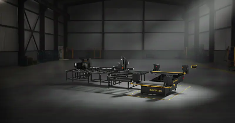
PVC Plastic Profile Welding System
The PVC Plastic Profile Welding System: Backbone of Modern Manufacturing
The plastic profile welding system is one of the most fundamental and technologically demanding components in modern industrial manufacturing. Wherever hollow-chamber or solid profiles made of thermoplastic plastics must be joined permanently, airtight, and with structural reliability, these systems form the heart of production. Their most prominent and most advanced application is in the manufacture of window and door frames made of PVC (polyvinyl chloride), but their importance extends far beyond that into numerous industries.
A “system” is far more than a single machine; it is an integrated setup that typically comprises multiple highly specialized components—from the welding unit itself to transfer systems and the indispensable post-processing via a corner cleaning machine. In an era defined by automation, precision, and flawless aesthetics, the performance of a plastic profile welding system determines the quality and profitability of entire production lines.
This comprehensive technical article examines every aspect of these complex systems. We dive deep into the physics of the welding process, analyze the different system types, discuss revolutionary developments from simple corner welding to fully automated zero-seam solutions, and consider both the economics and future trends of this essential technology.
What Is a Plastic Profile Welding System? A Detailed Definition
Before we analyze the complex details, we need a clear definition and boundaries. The term “system” implies a setup that goes beyond a single machine.
Core Components: More Than Just a Welding Machine
A plastic profile welding system—especially in the window industry—is an integrated production line or cell. Its primary task is to create a closed frame from cut individual profiles. Typical core components include:
The welding unit: The heart of the system that creates the thermal joint (e.g., a four-head welding machine).
Transfer systems: Buffer sections, cooling conveyors, turning and transfer devices that safely move the freshly welded, still unstable frame to the next station.
The corner cleaning machine (deburring unit): A CNC-controlled machine that removes the “weld bead” (excess material) produced during welding and finishes the corners functionally and aesthetically.
In a fully automated configuration, robots for loading and unloading can also be part of the system.
The Goal: A Material-Bonded, Monolithic Joint
The physical goal of any plastic profile welding system is to create a material-bonded connection. Unlike a form-fit (e.g., screws) or force-fit (e.g., clamping), the molecular chains of the parts to be joined are rewoven by melting (plastification) and subsequent pressing together under pressure (interdiffusion). After cooling, a homogeneous, monolithic joint is formed that ideally has the same or even higher strength than the base material.
Why Welding? Differentiation from Other Joining Techniques
Choosing welding for plastic profiles is not arbitrary; it is a technical necessity derived from geometry and material properties.
Mechanical joining (screws/corner brackets): Most plastic profiles (especially in window construction) are hollow-chamber profiles. These chambers are critical for thermal and acoustic insulation. A mechanical corner joint like those used with aluminum would not seal the chambers. The result: insufficient water and air tightness, significant thermal bridges (poor U-values), and often inadequate corner strength.
Adhesive bonding: Industrial bonding is complex. It requires extremely clean surfaces, precise dosing, long curing times (which massively slow cycle times), and it is prone to processing errors. Long-term resistance to UV and weather is often inferior to that of a homogeneous welded joint.
Welding eliminates these drawbacks: it is extremely fast (cycle times of a few minutes per complete frame), absolutely tight, highly stable, and perfectly automatable and monitorable.
Dominant Materials: Which Plastics Are Welded?
A plastic profile welding system must be tailored to a specific material because every thermoplastic has its own melt behavior.
The Industry Standard: Polyvinyl Chloride (Rigid PVC / PVC-U)
By far the most important material for welded profile frames is rigid PVC (PVC-U). Reasons for its dominance (particularly in construction and windows) include:
Excellent weather and UV resistance
High chemical resistance
Low flammability
Very good thermal insulation properties (low thermal conductivity)
Excellent processability (extrusion and welding)
Strong price-performance ratio
Nearly all highly automated welding systems (such as four-head lines) are optimized for processing PVC window profiles.
Technical Profiles: Polyethylene (PE) and Polypropylene (PP)
Beyond PVC, other thermoplastics are also welded in profile form—often with different machine types (e.g., in pipeline construction):
PE-HD: Used for piping, apparatus, and tank construction as well as highly durable technical profiles. Welding PE requires different parameters (lower temperature, different times) than PVC.
PP: Used in apparatus engineering and for chemically resistant ducting or media conveyance.
Material Challenges for the System
Welding parameters (temperature, time, pressure) are material-specific. A system designed for PVC cannot simply weld PP. Temperature windows, melt viscosity, and cooling characteristics differ fundamentally. That’s why advanced frame welding systems focus almost exclusively on PVC.
Historical Development: From Handwork to Fully Automated Lines
The history of plastic profile welding systems mirrors the industrialization of window manufacturing.
Beginnings: Manual Joining and Simple Single-Head Devices
When PVC windows emerged in the 1960s, corner joints were the Achilles’ heel. People experimented with solvent (solvent welding) or used primitive heating devices. Early “welders” were simple, manually operated single-head fixtures. An operator clamped the profiles, slid a heating plate between them, and pressed the parts together by hand. Quality depended heavily on the operator and was often inadequate.
The 1970s/80s Revolution: PLC, Pneumatics, and Multi-Head Machines
Oil crises in the 1970s triggered a boom in thermally insulating PVC windows. Manual production couldn’t keep up. Pneumatic clamping and feed cylinders replaced manual force. The real revolution was PLC control, enabling precise, repeatable control of the key parameters (temperature, time, pressure).
In parallel, two-head and finally four-head machines were developed. Four-head welders could weld all four corners of a frame simultaneously, dramatically improving productivity and, crucially, frame dimensional accuracy and squareness.
Birth of the “System”: Integrating the Corner Cleaning Machine
With faster welding, post-processing became the bottleneck. The weld bead had to be laboriously removed by hand (chisel, file). The logical step was the corner cleaning machine (deburring CNC), automatically finishing the corners.
Coupling a four-head welder with a buffer/cooling section and a corner cleaner marked the birth of the plastic profile welding system as an integrated weld-and-clean line.
The Aesthetic Revolution (from ~2010): Zero-Seam Technology
The most recent revolution was aesthetic. With the rise of colored and foil-laminated profiles, the “cleaning groove” left by milling became a visual defect. The answer was zero-seam technology, enabling a seamless outside corner.
The Heart of the System: Welding Technology in Detail
Although the system comprises many elements, the welding unit is its heart. The dominant process is hot-plate butt welding (often called mirror welding).
The Welding Cycle Step by Step
A modern machine’s cycle, often only a few minutes, follows a finely choreographed physical process.
Phase 1: Clamping and Positioning
Cut profiles (e.g., miters at 45°) are loaded. Pneumatic or hydraulic clamps fix them in place. The clamping tools are contour jaws—negative forms of the profile geometry.
Why it matters: PVC hollow-chamber profiles are relatively unstable. Flat clamping would crush chambers under high forging pressure. Form-fitting contour jaws support the profile inside and out, preserving shape. Positioning accuracy is within hundredths of a millimeter.
Phase 2: Heating (Plastification)
A massive, precisely temperature-controlled hot plate (“mirror”) moves between the profile ends (typically 240–260 °C for PVC-U). The profile ends are pressed against the plate with a defined heating pressure. Heat penetrates for a defined heating time (e.g., 20–40 s), plastifying material to a defined depth (≈2–3 mm). The plate is coated with PTFE (Teflon) to prevent sticking.
Phase 3: Critical Changeover Time
The profiles retract slightly, the hot plate exits very quickly (often <2 s). This time must be minimized; otherwise a skin forms on the melt surface (cooling/oxidation), inhibiting molecular diffusion and causing a “cold joint.”
Phase 4: Forging and Cooling
Immediately after plate removal, the plastified ends are pressed together with high forging pressure. This expels air, ensures intensive interdiffusion, and squeezes out excess melt as a weld bead. The joint is held under pressure (or holding pressure) for a defined cooling time until the melt solidifies below Tg. Releasing too early risks tearing the joint or warping the frame.
The “Holy Trinity”: Temperature, Time, Pressure
Weld quality depends on the precise interplay of these three parameters. For every profile system (wall thickness, number of chambers, material recipe), exact values must be determined and stored in the controller as a “recipe.” Deviations of only a few degrees or seconds can mean the difference between a perfect joint and expensive scrap.
The Weld Bead: Quality Indicator and Reason for Removal
A uniform, fully formed bead indicates a correct process—but it also interferes functionally (glass and hardware installation) and aesthetically (visible faces). Hence the system’s second core component is indispensable.
The Second Core Component: The Corner Cleaning Machine (Deburring)
A plastic profile welding system is only as good as its finishing. Welding creates the bond; cleaning creates function and appearance.
Why Is “Cleaning” Essential?
Functional (inside): Beads in glazing rebates, hardware rebates, and gasket grooves would obstruct glass, gaskets, and locking mechanisms.
Aesthetic (outside): Beads on visible faces are unsightly.
How a CNC Corner Cleaner Works
The welded frame is (often automatically) fed, clamped, and centered. Using a variety of tools, the machine processes the fresh corner:
Top/bottom knives: Remove flat beads from visible faces.
Inside-corner knives (rebate knives): Cut beads out of complex inner geometries (glazing rebate, gasket grooves).
Milling units (contour milling): With traditional welding, a contour mill follows the outer profile to remove the external bead—leaving the characteristic cleaning groove.
Drills/groove cutters: Clean functional grooves and drill, e.g., drainage holes.
Programming is complex: the CNC must know each profile’s exact geometry.
The Aesthetic Revolution: Zero-Seam Technology
The biggest innovation in the last 15 years addresses the aesthetic challenge of colored and foil-laminated profiles.
The Problem: “Cleaning Groove” on Colored Profiles
As colored and wood-grain foils boomed, traditional milling removed not only the bead but also foil or color layer—exposing a bare (often white or brown) groove at the miter. The old stopgap was manual touch-up with paint pens—costly and error-prone.
The Solution: Zero-Seam (V-Perfect / Seamless Welding)
Zero-seam prevents uncontrolled bead formation on visible faces in the first place.
Technical approaches (often combined):
Mechanical limitation (e.g., 0.2 mm): Knives/stops on the hot plate or clamps limit melt displacement to a barely visible line.
Forming/displacement: Moving tools actively push melt inward (into chambers) or into non-visible areas (e.g., gasket groove) during forging.
Thermal forming: Special, often heated tools “iron” the miter during cooling so that foils meet perfectly at the edge.
Does Zero-Seam Remove the Need for Cleaning?
Yes and no. Zero-seam eliminates external aesthetic milling. The corner cleaner is still required for functional inside cleaning (rebates, grooves) because material is displaced inward. The line isn’t shorter, but manual paint touch-up disappears entirely.
Types of Welding Units Within the System
The system’s performance is defined by its welding unit; its number of heads sets productivity.
Single-head welders: Rarely part of an in-line system; used as flexible stand-alones.
Pros: Lowest investment, maximum flexibility for specials (slopes, arches).
Cons: Very low throughput; frame geometry depends on operator.
Two-head welders: For special tasks or medium operations.
Pros: Much faster than 1-head, more flexible than 4-head; ideal for mullions/T-joints.
Cons: Still needs multiple steps to close a frame.
Four-head welders (industry standard):
Pros: Extremely high productivity (often <3 min per frame), best dimensional accuracy and squareness (frame clamped as a whole).
Cons: Higher capex; less flexible for unusual angles (modern machines mitigate this).
Six- and eight-head machines target mass production (e.g., frames with integrated mullions or two sashes at once): maximum output but very high capex and low flexibility.
Quality Assurance, Maintenance, and CE Safety
A plastic profile welding system is complex and reliable only when perfectly calibrated and maintained.
Typical Welding Defects (Troubleshooting)
Cold joint (low strength): Brittle, crystalline fracture surface.
Cause: Temperature too low, heating time too short, or changeover too long (surface cooled).Burnt joint (visual + embrittlement): Yellow/brown discoloration, brittle material.
Cause: Temperature too high or heating time too long (thermal degradation).Angle/dimension errors (warpage): Frame not square or off-size.
Cause: Mechanical misalignment, contaminated contour jaws (bad clamping), cooling time too short.
The Importance of “Profile Recipes” (Parameter Management)
Each profile system differs in geometry, wall thickness, and formulation. A modern system must store and recall hundreds of recipes (temperature, times, pressures) to guarantee consistent quality.
Regular Maintenance: PTFE Films, Clamping Tools, Guides
PTFE (Teflon) on hot plates: Critical wear item; inspect and clean daily. Burnt PVC residues impair heat transfer and appearance; replace regularly.
Contour jaws: PVC dust/chips in contours prevent correct seating → dimensional errors.
Guides, pneumatics/hydraulics: All moving parts must run smoothly and precisely.
Non-Negotiable CE Compliance: Protecting People and Operations
Industrial welding systems involve >250 °C, high forces (often several tons), and fast-moving assemblies. Compliance with the EU Machineryective (CE) is essential: enclosures, light curtains, two-hand controls (during loading), and redundant emergency-stops. With extensive project experience, companies like Evomatec ensure inspections cover CE safety and manufacturing quality meticulously.
Economics: Cost, ROI, and Efficiency
Investing in a complete plastic profile welding system is one of the largest single outlays for a pvc door manufacturing operation.
Capex: From Single-Head to Fully Automated Line
Indicative ranges:
New, high-quality single-head (angle-adjustable): €15,000–30,000
New two-head: €35,000–70,000
New four-head (standard, traditional): €90,000–160,000
Integrated weld-and-clean system (4-head, traditional): €180,000–250,000
Integrated weld-and-clean system (4-head, zero-seam, automation): €250,000–500,000+
Opex: Energy, Labor, Wear Parts
Energy: Heating multiple massive hot plates is the main consumer.
Labor: Biggest savings lever. An automated line needs a single operator for loading/monitoring; multiple single-heads would require several operators.
Wear: PTFE films, knives, mills for the corner cleaner.
ROI Example
Target: 60 frames/day in an 8-hour shift.
Single-head: ~3–4 min per corner → 12–16 min per frame → 720–960 min total. Not feasible on one machine; would need ≥2 machines and 2 operators plus manual cleaning.
Four-head weld-and-clean line: ~3 min per frame → 180 min total.
→ Only ~3 hours of machine time; one operator manages 60 units with significant capacity left (150+ per shift).
Conclusion: The line pays back quickly via 2–3 saved FTEs (welding + cleaning) and much higher output.
New vs. Used: Opportunities and Risks
Wear: Worn guides/spindles → accuracy issues.
Obsolete controls: Spares for old PLCs may be unavailable.
Technology: Used systems rarely feature zero-seam.
Safety: Older machines may not meet current CE standards.
Expert inspections are essential. With deep project experience, providers like Evomatec ensure thorough, CE-compliant evaluations to avoid bad investments.
The Future: Plastic Profile Welding Systems in Industry 4.0
Connectivity and the “Smart Factory”
The weld-and-clean line integrates with ERP/PPS. A barcode at infeed identifies the profile; the system (welder + cleaner) automatically loads the correct recipe (welding parameters and cleaning contours) and sets dimensions.
Predictive Maintenance and Remote Service
Systems monitor themselves—counting PTFE cycles and signaling replacements before quality drops. Online connectivity enables remote diagnostics and fixes without travel.
Robotics and the “Manless” Welding Cell
Full automation: robots load profiles from the saw, unload welded frames, hand them to the corner cleaner, and stack finished parts.
Energy Efficiency and Sustainability (Recyclate Welding)
Faster heat-up, better insulation, and reliable welding of recyclate-core profiles (different melt behavior) are key trends.
AI-Driven Process Optimization and Quality Control
Vision systems can monitor melt formation and final zero-seam in real time. AI can detect deviations (e.g., due to a material batch issue) and dynamically adjust parameters to guarantee perfect results.
Selecting the Right System: A Strategic Decision
Needs Analysis: Throughput, Flexibility, Aesthetics
Throughput: Units per shift define head count (1/2/4) and automation level (stand-alone vs. line).
Flexibility: Many special shapes (slopes, arches) vs. standard rectangles?
Aesthetics: Processing colored/foil-laminated profiles? Zero-seam is now almost a must.
The Value of an Experienced System Partner
Choosing and integrating the right system (saw → welding → hardware → logistics) requires deep process knowledge. Experienced partners like Evomatec analyze not only the machines, but the entire workflow to eliminate bottlenecks. Extensive project experience ensures that planning, commissioning, and acceptance are executed with maximum attention to quality and CE-compliant safety—protecting uptime and your investment.
FAQ – Frequently Asked Questions About Plastic PVC Profile Door Welding Systems
What’s the difference between a welding machine and a welding system?
A welding machine (e.g., a four-head welder) is the single unit performing the thermal joining. A welding system (or weld-and-clean line) is the integrated setup: at minimum the welding machine, a transfer/cooling section, and the downstream corner cleaning machine that finishes the welds.
What is “zero-seam,” and do I need it?
Zero-seam (also known as V-Perfect) is a modern welding technology that produces an optically seamless outside corner without the typical visible weld bead. If you produce only white profiles, it’s a nice-to-have. For colored or foil-laminated profiles (e.g., woodgrains, anthracite), zero-seam is a decisive competitive advantage—eliminating time-consuming manual touch-up and delivering superior aesthetics.
How long is a complete system cycle?
Cycle time is set by the welder. A complete welding cycle (clamp, heat, forge, cool) on a modern four-head machine for a standard frame typically takes 1.5–3 minutes. The corner cleaner must be specified to finish all four corners within that same takt to avoid a bottleneck.
Request a free consultation:www.evomatec.com